Design of grayscale display scheme for HD LED display
- author:
- 2024-05-25 14:13:23
Information display is an important part of information science and technology. As a bridge for human-computer interaction, photoelectric comprehensive display is increasingly widely used. For a long time, information display technology has been stuck in the era of cathode ray picture tubes (CRT). However, as a vacuum device, CRT has some inherent shortcomings, which limit its application scope in some fields. In order to solve the problems caused by CRT displays, the research and development of flat panel displays (FDP) are being stepped up at home and abroad. Among the many FDPs, light emitting diode (LED) displays have attracted much attention because of their unique advantages: low working power supply, fast response speed, wide operating temperature range, low power consumption of all-solid-state devices, small size, impact resistance, high reliability, long life, etc. At the same time, since the LED itself is a semiconductor device, it is fully compatible with IC circuits, and its control and driving circuits are easy to integrate into the flat panel display, thereby further reducing the size of the display and facilitating the multiplexing of signals. Based on in-depth research on the luminescent characteristics of LED devices, this paper introduces a solution to realize gray display on high-position high-density LED flat panel displays, and verifies the feasibility of this solution through experiments. Experimental results show that the LED grayscale display achieved by this scheme can take into account both the brightness and grayscale of the display.
1. Principle of LED dot matrix gray level generation
Each pixel of the LED dot matrix consists of three colors of LEDs, red (R), green (G), and blue (B), corresponding to one pixel of the video image. When displaying synchronously with a computer CRT, if the luminous brightness of the red, green and blue LEDs of each pixel of the LED dot matrix changes with the changes in R, G and B signals at the corresponding pixel points of the CRT, the corresponding CRT image can be displayed synchronously. If gray levels are used to describe the brightness changes of monochrome LEDs, the more gray levels, the richer the color and clearer the layers of the image. The forward volt-ampere characteristic of the LED is roughly the same as that of ordinary diodes. No current passes before the voltage turn-on point. When the voltage exceeds the turn-on point, it shows conduction characteristics. At this time, the relationship between forward current I and forward voltage U is as follows:
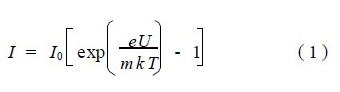
其中,m 为复合因子,I0 为反向饱和电流,UT=kT/e 称为温度电压当量,在热力学温度 T=300K 时,UT=26mV。In wide-gap semiconductors, when I<0.1mA, the spatial recombination current through the deep level in the junction dominates, m=2; when the current increases, the diffusion current dominates, m=1. U is the applied voltage.
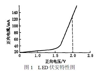
由图 1 可以看出,LED 从导通开始直到其不被烧毁的最大电流为止,其伏安特性通常是线性的。In this linear region, the luminous intensity of the LED is basically proportional to its current intensity. There are two methods to achieve LED brightness control:
- By adjusting the forward current of the LED, the brightness modulation of the LED is achieved. For example, by adjusting the forward conduction current of an LED in a certain step size, its luminous brightness can be divided into several gray levels. However, the driving circuit required in this method is too complex and not feasible in practical applications, so this will not be discussed here.
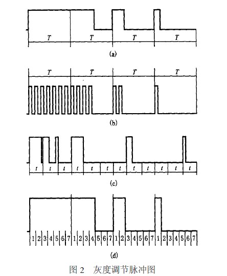
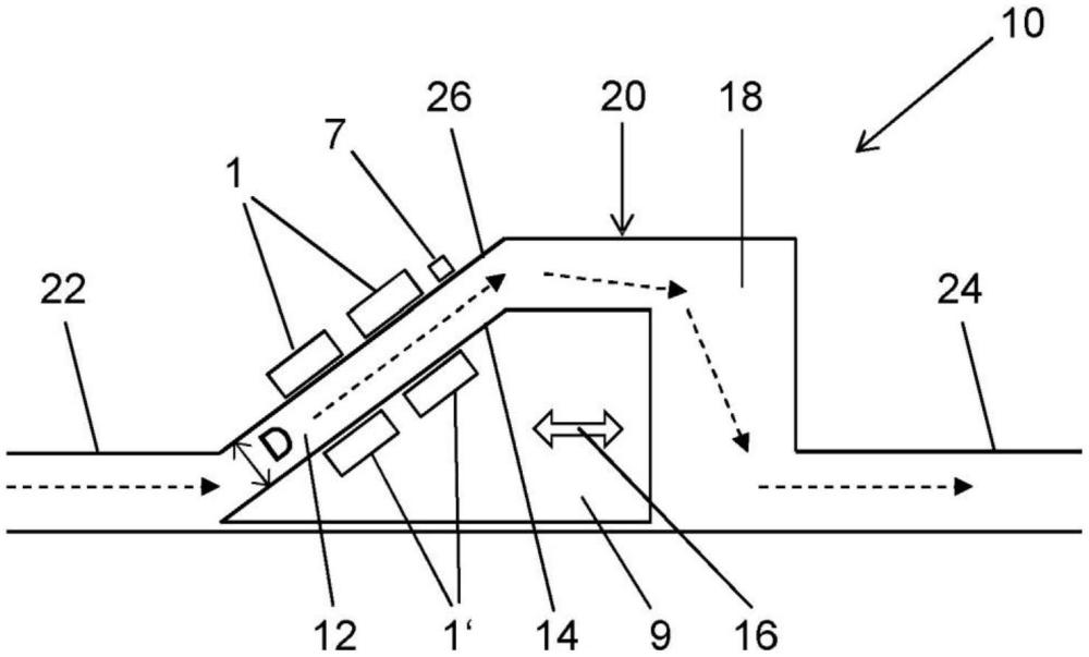
- Controls the ON time of the LED per unit time. LEDs have fast time response characteristics, up to tens of megahertz, and can be driven to emit light in pulses. For example, driving an LED with a pulse of 1MHz, a duty cycle of 0.25%, and a peak current of 1A is consistent with driving an LED with a DC of 25mA. Obviously, by adjusting the duty cycle of the driving pulse, different gray levels can be obtained. Then, if the discrete image data of each pixel of the CRT image signal is used to control the conduction time of the corresponding LED, a multi-gray-level display image can be obtained. Figure 2 shows that during the cycle time T, pulses with duty cycles of 1, 4/7, 2/7, and 1/7 respectively drive the LEDs. Obviously, the obtained brightness ratio is 7:4:2:1, so that the highest gray level is 7, and a total of 8 gray levels can be obtained.
CRT images are refreshed at frame rate. Each frame of image can be represented by a matrix of M rows and N columns, corresponding to a frame of video image with M N pixels.
CRT 图像是按帧频来刷新的,每一帧的图像可以用一个 M 行 N 列的矩阵来表示,对应着一帧 M× N 像素点的视频图像。Each image is different, and the values of the matrix elements will also change accordingly. The expression of the matrix is:
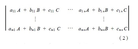
其中,A、B、C 代表着具有单位亮度的 R、G、B 三原色,系数 aij、bij、cij 为零和正整数,它决定着混成该像素点颜色所需 R、G、B 三色的亮度份额。If the brightness of the three primary colors R, G, and B contained in the white level brightness of the image is equally divided into N levels, then each brightness is A, B, and C, i.e., unit brightness. The values of aij, bij, and cij are from 0 to N respectively, which means that the color of the pixel point corresponding to the element can be blended with the aij component red, the unit brightness of bij component green, and the unit brightness of cij component blue. According to the matrix algorithm, matrix (2) can be expressed as:
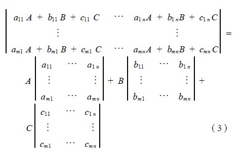
它表示一场图像可以分解为 R、G、B 单色图像,同样,用 R、G、B 单色图像在空间或时间上叠加,也可以恢复原来所对应的彩色图像。
The terms in equation (3) represent red, green and blue monochrome images respectively, and have several gray levels. If the values of aij, bij, and cij range from 0 to N respectively, then the gray level of each monochrome image is N+1. According to the matrix algorithm:
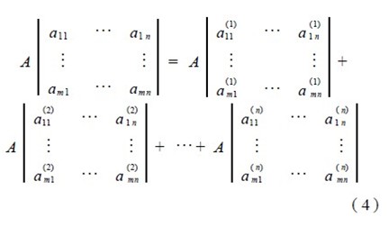
其中,aij(n)=0 或 1,且 aij=aij(1)+aij(2)+...+ aij(n)。
It can be seen from Equation (4) that a monochrome image data matrix can be decomposed into the sum of several binary matrices (each element in the matrix is 0 or 1), each binary matrix representing a monochrome binary image with unit brightness. Then, the meaning of equation (4) is: a monochromatic image with (N+1) gray level can be formed by superimposing several N monochromatic binary images with unit brightness in time. Obviously, superimposing in space is unrealistic. This means that the monochrome video image of a television field can be divided into several monochrome binary images, and then these monochrome binary images can be displayed in sequence. According to the integration effect of the human eye, the original monochrome video image can be reproduced. By the same method, R, G, and B monochrome video images are restored at the same time, and then superimposed in space to obtain a color video display image.
Specifically, if the gray level of each monochromatic pixel is N+1, the gray levels from low to high are 0, 1,..., N, a series of N-bit 0,1 control codes corresponding to each gray level is defined for each gray level. In each control code, the total number of 1s is equal to the number of its corresponding gray level, that is, the higher the gray level, the more 1s are in the control code.
Each display cycle of the LED is then divided into N segments at equal intervals. Each segment uses a one-bit control code to control the ON and OFF of the LED." 1" means to control the LED on, and" 0" means to control the LED off. Since the number of 1s in different gray levels is different, the time for which the LEDs are turned on is different within a cycle, and the difference in brightness is caused through the integral effect of human vision.
By analogy, a monochrome picture displayed by the CRT is divided into N fields and displayed on the LED dot matrix screen. The display time of each field is TPN. In each field, each pixel is controlled by its corresponding control code to turn on and off the LED. Through the integrated effect of vision, the gray effect of the entire picture is generated.
3. Hardware implementation of the LED control board
The hardware design block diagram of the LED board is shown in Figure 3.
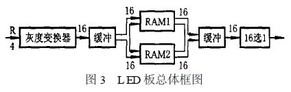
CRT 的红色信号经采样量化后形成红色 4 位二进制数,因此经量化的亮度有 16 级。For example, a frame of a CRT image is displayed in 15 fields on an LED dot matrix screen, and different brightness levels are formed by controlling the number of times LED pixels are lit up in the 15 fields. If a certain pixel in the 15 fields is not lit up at all, it is black; if it is lit up once, it will show that the image brightness is only higher than black; if it is lit up twice, the brightness will be one level higher; if it is all lit up, it will be the brightest. In the actual circuit, considering the complexity of the circuit, the LED screen is divided into 16 fields for display, and the first field is never lit. This will of course lose some brightness, but simplify the design.
TAG:
Guess you want to see it


Popular information
-
To solve 2 problems, Octavia Optoelectronics and Ames Osram announced new patents
-
Evolution history of led displays from monochrome to full-color to small-pitch
-
A new method for detecting brightness and chroma of outdoor full-color LED display
-
Design of grayscale display scheme for HD LED display
-
From modules to large screens, the entire process of LED display installation is introduced
-
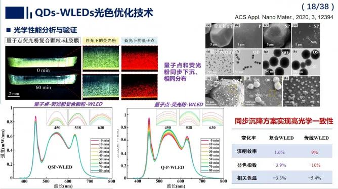
Efficient and reliable quantum dot white LED packaging and thermal management
-
Analysis of factors affecting display prices
-
"Quick Guide for LED Display Industry Experts"

-
What kind of LED full-color screen can meet indoor and outdoor needs?

-
Introduction to LED process technology--Application of LED display driver chips
the charts
- Liaocheng University and Soochow University collaborate to make progress in the research field of bl
- Hot research! How will the future development of LED displays achieve a leap?
- How to better select and use dedicated LEDs for full-color displays
- Introduction to LED process technology--Application of LED display driver chips
- Design of grayscale display scheme for HD LED display
- A new method for detecting brightness and chroma of outdoor full-color LED display
- Analysis of six characteristics of LED display application phenomena
- What are the quality and installation requirements for installing LED displays in multi-functional s
- What kind of LED full-color screen can meet indoor and outdoor needs?
- Analysis of factors affecting display prices