From modules to large screens, the entire process of LED display installation is introduced
- author:
- 2024-06-07 13:38:20
With the rapid development of modern technology, LED displays are becoming more and more widely used in various fields. Whether it is commercial advertising, stage performances or information displays, LED displays play an important role. To ensure that the LED display can stably and clearly present content, its installation process is crucial. This article will detail the entire process of LED display installation from modules to large screens, hoping to provide reference and help for those in need. First, we need to make a structure based on an example of the existing small screen we are making. Purchase 4 pieces of 44 square steel and 4 pieces of 22 square steel (both 6 meters long) from the market. First make a T-frame with 44 square steel (can be customized according to actual conditions). The size of the large frame is 4850mm 1970mm, because the size in the small frame is the size of the screen, and the square steel is 40mm, so this size is obtained.
During welding, try to use a steel angle ruler to weld it at a 90-degree angle. After the T-frame is completed, start welding small square steel on it. The internal size of the small square steel is 4810mm to 1930mm, and the corners and middle parts are cut into small pieces with the remaining 44 square steel for welding the square stainless steel.
After the small frame is completed, start welding the back strips, measure the first two pieces with a plate to determine the size, and then weld them all the way down. The back is 40mm wide and about 1980mm long, as long as the two ends can be welded well. After the welding is completed, the frame can be installed in the hall (depending on the back) and two angle iron hooks can be made on the top of the wall. 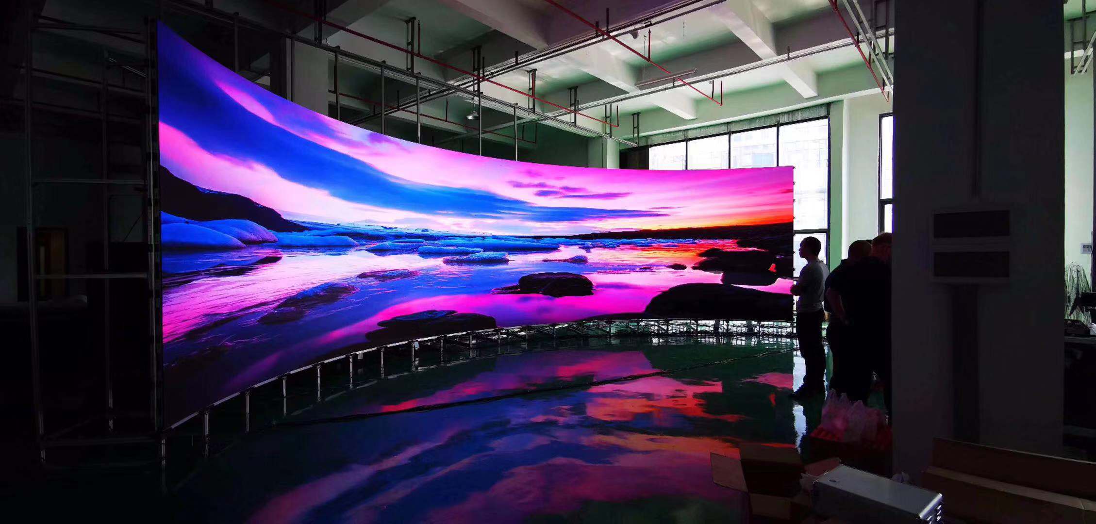
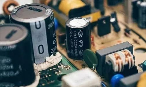
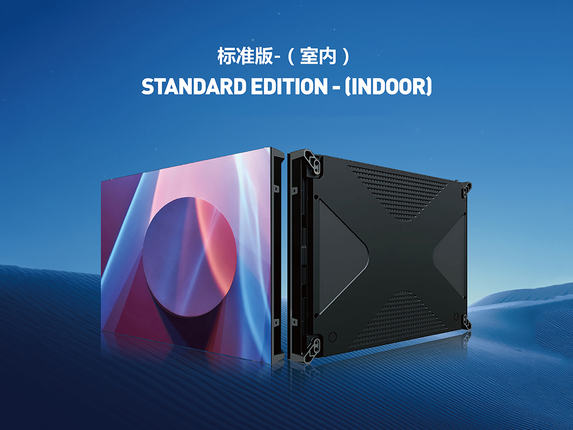
Next, install the power supply, control card, and template. After the rack is hung, a gap of about 10mm is left around. Because the indoor screen cannot be made into a box frame with a fan, this 10mm gap is simply relied on for ventilation. When installing the power supply, first connect two finished power cables. The 5V output must be good, otherwise the power cables, modules and control cards will be burned out. Each finished power cord has two connectors, so each power cord can carry four modules. Then, a 220V connection is made between the power supplies. As long as each row is strung together with a 2.5 square piece of flexible copper wire, each group of 220V power cables will be connected to the open terminals of the distribution cabinet. The cables from the distribution room to the LED display cabinet must be laid out before the screen is installed. After turning on the power supply, install the control card. Here, the control card uses a synchronous receiving card. The layout of the entire power supply and control card, as well as the LED display, has power supply and system wiring diagrams from the factory. As long as the wiring diagram is strictly followed, there will be no error. The average engineer himself can also estimate the way to get out based on the number of power supplies and cards.
When receiving cards are linked to modules, each card has three rows of modules, for a total of 36 boards. In this way, one card is installed every three rows, and 5V is taken from the nearest power supply to power the card. Note that these five cards are connected using network cables, and the network port near the power connector is the input port. The first card on the right is also the top card. The input is connected to the gigabit network card of the computer, and then the output network port is connected to the input port of the second card. The output port of the second card is connected to the input port of the third card. Connected in turn until the fifth card, the input is connected to the output of the fourth card, and the output is empty.
Before installing the module, it is necessary to use stainless steel hemming, which is only for aesthetic appearance and is also a requirement of the installation unit. I found a stainless steel maker to measure the size. It was estimated that after measuring the steel structure, the size was enlarged by 5mm, so that the stainless steel edge could be blocked and convenient installation.
When installing the module, the upper module can be opened by tightening the stainless steel edges. It is recommended to install the module from the bottom up, starting from the middle to the sides. There is much controversy about this installation method. The main purpose of installation from the bottom is to keep horizontal and vertical levels within normal control ranges. Especially when the screen area is large, it is easier to lose control. In particular, the requirements for small spacing are extremely high, and some gaps need to be fine-tuned when they do not meet the requirements. Engineers whose installation spacing is too small know that even if the precision mold comes out of the module or box, there will still be errors. Misplacement of several threads can cause the entire thread to be misplaced. Secondly, installation from the middle to both sides can be divided into two groups or even four groups to carry out the work, saving installation time. Even if you encounter a problem of misplacement in installation, it will basically not affect the progress of another group of personnel. Bring your own tools. If the cable cable is damaged, cut it again. Just press the ends and install the fixing clip. Many times, because the back strips support uneven modules, the line cards must be cut off during installation. When the cable is inserted into the module, the red edge is up and the arrow of the module is up. If there are no modules marked with arrows, the printing on the modules must face up. The connection between modules is that the input in front of the module connects the output behind the previous module.
Finally make adjustments. After installing the four-wire module card, turn on the test power supply. Any problem is solved in time, because if the next set is installed, this card will be overwritten and cannot be tested. In addition, if the installation continues, the problem will not be discovered in time. If you install all modules, then find the problem points, and remove the installed modules, the workload will be much greater. There is a test button on the control card. You can use this method to test it first when you just power on. If the installation is normal, the screen will display red, green, blue, line, field, and dot information in turn, and then test the control computer again, mainly to test whether the network cable communicates normally. If it is normal, install the next group until the installation is complete.
The installation of LED displays is a complex and meticulous task that requires strict operation in accordance with the steps and requirements. Only in this way can we ensure that the LED display operates stably and show a clear and gorgeous picture. It is hoped that through the introduction of this article, everyone will have a deeper understanding and understanding of the installation process of LED displays, and provide useful reference and guidance for actual installation work.
The above content is for reference only, and the specific installation process may vary depending on actual conditions. When installing LED displays, it is recommended to seek professional help and guidance.
TAG:
Guess you want to see it

Popular information
-
How to better select and use dedicated LEDs for full-color displays
-
"Eight technical controls to ensure the quality of LED displays"
-
Introduction to LED process technology--Application of LED display driver chips
-
Causes and solutions to LED display control card failures
-
Liaocheng University and Soochow University collaborate to make progress in the research field of bl
-
Evolution history of led displays from monochrome to full-color to small-pitch
-
Analysis of factors affecting display prices
-
Efficient and reliable quantum dot white LED packaging and thermal management
-
Technical Chapter| What do you know about LED display device packaging technology?
-
Design of grayscale display scheme for HD LED display
the charts
- Liaocheng University and Soochow University collaborate to make progress in the research field of bl
- Hot research! How will the future development of LED displays achieve a leap?
- How to better select and use dedicated LEDs for full-color displays
- Introduction to LED process technology--Application of LED display driver chips
- Design of grayscale display scheme for HD LED display
- A new method for detecting brightness and chroma of outdoor full-color LED display
- Analysis of six characteristics of LED display application phenomena
- What are the quality and installation requirements for installing LED displays in multi-functional s
- What kind of LED full-color screen can meet indoor and outdoor needs?
- Analysis of factors affecting display prices